The voltage signal from the danger zone, the isolated transmission output single or dual independent current / voltage signal to a safe area, can also be configured in the security zone communication interface for serial communication network. It is intelligent safety barrier products, users can, or computer programming through a dedicated product for this type of input signal and output range settings.
Main technical parameters:
General technical data please refer to the manual, "General Index."
Ex mark: Ex (ia) Ⅱ C
Input / Output Accuracy: ± 0.2% × F.S
Danger zone to allow the input signal:
DC :0-5V ,1-5V ,0-10V
Input Impedance: 500KΩ
Signal type and range in the order determined at the time, but also their own programming *, but the choice of 0-10V input voltage can not select another type.
Output signal to the security zone:
DC :0-10mA ,4-20mA ,0-5V ,1-5V ,0-10V
Signal type and range in the order determined at the time, but also their own programming *.
Communication (only in safe areas): RS232 or RS485 interface, see the manual "communication technology." Communication function with non-elected second output.
Power Supply: DC 24V
Power:
1.9W (20mA Single Output, 24V powered)
2.4W (20mA Dual Output, 24V powered)
Dimensions
W × H × D: (22.5 × 100 × 115) mm
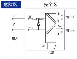
National Instruments certified explosion-proof safety supervision and inspection station parameters: (9,10 terminals) Uo = 15V, Io = 1mA, Co = 0.58μF, Lo = 1000mH
Scope:
From the transmitter, an instrument, secondary instruments, such as the DC voltage signal.
Please join in this manual to install the "appearance and installation."
Calibration:
This product uses the intelligent digital design, to ensure the accuracy of long-term requirements in the scope of this manual. For calibration, please matching dedicated programmer (economic) to operate. Specific operation and calibration, please refer to the manual "calibration and programming."
Selection Method:
| Model |
Description |
| JG-GLA- |
4 |
× |
× |
× |
× |
safe testing voltage input terminal, single, dual output |
| end of the first output operation |
1 |
|
|
|
4-20mA |
| 2 |
|
|
|
1-5V |
| 3 |
|
|
|
0-10mA |
| 4 |
|
|
|
0-5V |
| 5 |
|
|
|
0-10V |
| end of the second output operation |
|
|
|
default without second output |
| 1 |
|
|
4-20mA |
| 2 |
|
|
1-5V |
| 3 |
|
|
0-10mA |
| 4 |
|
|
0-5V |
| 5 |
|
|
0-10V |
| operation terminal communication (no second choice the output function) |
|
|
default is no communication function |
| T1 |
|
485 communications (only one output) |
| T2 |
|
232 communications (only one output) |
| outer structure |
|
default communication structure |
| B |
bus-powered structure |
Help
The type and the corresponding output voltage range, please specify when ordering. If the user should make their own programming, matching the economy of the companies dedicated programmer or computer configuration and software interfaces. For details, please refer to the manual "programming and calibration technology. "
Wiring diagram
|