Smart operator, also known as smart terminal, then the system can automatically (or adjust the instrument) of a given signal and valve position feedback signal, according to the deviation between the two to adjust the output volume of the corresponding control, and replace the low-power servo Amplifier to directly drive the valve, which can be accessed in a variety of regulator or after the computer control system for spare instrumentation。
| ●功能特点 |
| |
| Automatic calibration and manual calibration |
| Automatic to manual switch without disturbance |
| Smart operator can control each analog output with the way all the way off control output; relays forward and reverse control, and all the way analog output for a variety of measurement and control situations |
| Multiple protection, isolation design, anti-interference ability, high reliability |
| Good software platform, with the secondary ability to meet the special features |
| Advanced modular structure, with a powerful instrument chip, feature set, the system is very easy to upgrade |
|
| |
●The main technical indicators |
| |
Basic Error: 0.5% FS or 0.2% FS ± 1 word |
Force Resolution: 1 / 20000, 14-bit A / D converter |
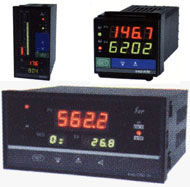
Display: LED digital tube while the four-row display, the display shows measured values, the lower display shows the valve position feedback value or output |
Sampling period:0.2S |
Alarm Output: Two alarm relay outputs, in regulating the signal or valve position feedback signal alarm, alarm, alarm mode, the sensitivity |
| were set, the relay output contact capacity AC220V/3A. |
| control output: (1) relay forward and reverse control contacts |
| (2)Pulse voltage output solid state relay(DC12V/30mA) |
| (3)Single phase / three phase thyristor zero trigger |
| (4)Single phase / three phase thyristor phase-shift trigger |
| (5)Analog 4-20mA ,0-10mA ,1-5V ,0-5V control output |
| Communication output: Interface - Isolated serial bi-directional communication interface RS485/RS422/RS232/Modem baud rate - 300 ~ 9600bps internal is free to set; |
| Feed output: DC24V/30mA |
| Power Supply: switching power supply 85 ~ 265VAC power 4W below |
|
| |
●Selection Table |
| |
Code |
Description |
JG-4000 |
|
|
Smart operator |
Dimensions |
A |
|
Horizontal160×80×125mm |
| A/S |
|
Vertical80×160×125mm |
| B |
|
Way96×96×110mm |
| C |
|
Horizontal96×48×110mm |
| C/S |
|
Vertical48×96×110mm |
| D |
|
Way72×72×110mm |
|
Control output |
L |
|
RelayControl output |
| X1 |
|
4-20mA Output |
| X2 |
|
0-10mA Output |
| X3 |
|
1-5V Output |
| X4 |
|
0-5V Output |
Communication Output |
P |
|
Micro-printer |
| R |
|
Serial CommunicationRS232 |
| S |
|
Serial CommunicationRS485 |
Power supply |
|
|
|
220VAC Power supply |
| W |
|
|
DC24V Power supply |
Adjust the input signal |
I1 |
|
Current signal:4-20mA、0-10mA? |
| V1 |
|
Voltage signal:1-5V、0-5V、0-10V |
Valve position feedback input signal |
I2 |
Current signal: 4-20mA、0-10mA |
| V2 |
Voltage signal:1-5V、0-5V、0-10V |
| Z |
Potentiometer:0-2KΩ |
|
|